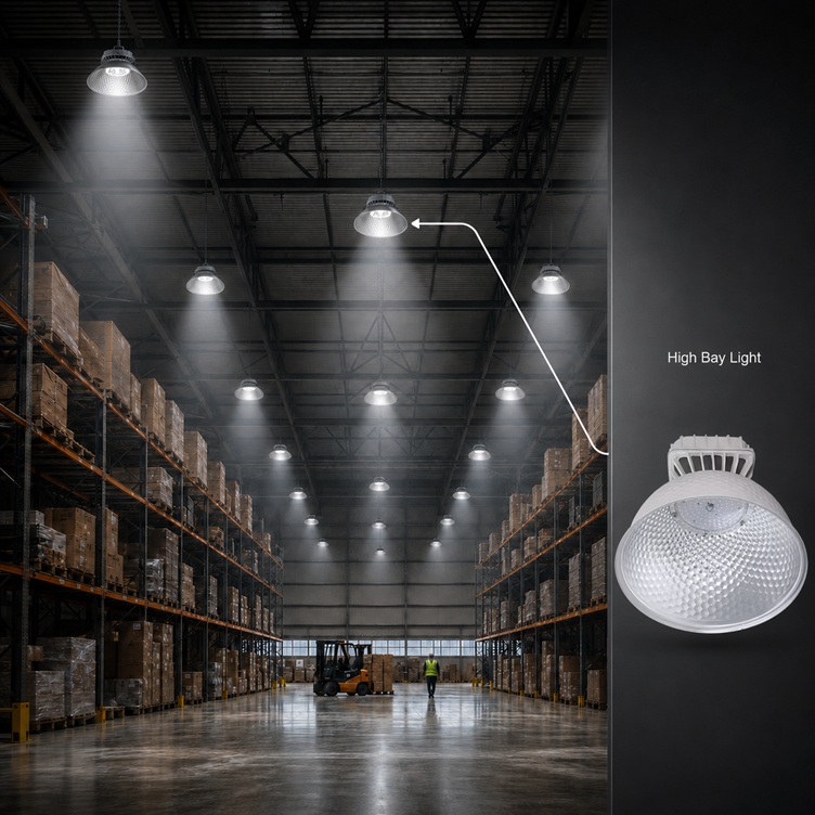
High bay light spacing follows one working rule: multiply the mounting height by a spacing-to-height ratio of 0.8 to 1.5, set by the fixture’s beam angle. At 10 m with 90° optics, that means one fixture roughly every 10–12 m in both directions. This guide gives you the complete method behind that rule: the lux targets to design for, the lumen method for fixture counts, a fully worked warehouse example, and the racking-aisle adjustments that generic guides skip.
Key Takeaways
- Spacing = mounting height × S/MH ratio: use 0.8–1.0 for 60° optics, 1.0–1.2 for 90°, 1.2–1.5 for 120°.
- Design to maintained lux with a maintenance factor (0.8 is the common default), not to day-one values.
- General warehousing needs 150–200 lx; order picking 200–300 lx; packing benches 300–500 lx.
- Racking aisles break the open-area rules: run fixtures along aisle centerlines with narrow or aisle optics.
- Rules of thumb scope the budget; sign off only on a DIALux calculation with the fixture’s real IES file.
Start With the Target Illuminance
Every high bay light spacing calculation starts from the required illuminance on the working plane, because spacing exists to deliver a lux target uniformly, not to satisfy geometry for its own sake. Typical maintained targets, based on EN 12464-1 practice and common warehouse specifications:
| Area | Maintained target | Notes |
|---|---|---|
| Bulk storage, low activity | 100 – 150 lx | Floor-level tasks only |
| General warehousing, forklift traffic | 150 – 200 lx | The default aisle spec |
| Order picking | 200 – 300 lx | Label reading drives it |
| Packing / dispatch benches | 300 – 500 lx | Task lighting zone |
| Fine inspection | 500 lx + | Consider local task lights |
| Cold storage | 150 – 300 lx | Verify fixture low-temp rating |
Two qualifiers matter more than the numbers themselves. First, these are maintained values: the level after the fixture has depreciated and gathered dust. Divide your day-one design by a maintenance factor, commonly 0.8, or the space will drift below specification within a few years as lumen output declines toward the fixture’s L70 rating. Second, uniformity is as binding as the average. A warehouse that averages 200 lx with dark bands between fixtures fails its purpose; aim for a minimum-to-average ratio of at least 0.4 in general areas and 0.5 where picking accuracy matters.
The Spacing-to-Height Ratio, and Where It Comes From
The spacing-to-mounting-height ratio (S/MH) compresses a fixture’s photometric behavior into one planning number. It answers: how far apart can fixtures sit, as a multiple of their height above the floor, before uniformity collapses?
| Beam angle | S/MH ratio | Best for |
|---|---|---|
| 60° (narrow) | 0.8 – 1.0 | Mounting above 12 m, racking aisles |
| 90° (medium) | 1.0 – 1.2 | General areas, 8–12 m mounting |
| 120° (wide) | 1.2 – 1.5 | Open floors below 8 m |
The physics is straightforward. A narrower beam angle concentrates candela downward, so each fixture covers a smaller floor circle but survives a higher mounting position; light from adjacent fixtures overlaps less, so they must sit closer together relative to height. Wide optics do the opposite: broad overlap tolerates wider spacing but wastes intensity at height.
Spacing = mounting height × ratio. Apply it in both directions for a square grid, or use unequal spacing along and across the building when the structural grid dictates.
One caution: S/MH assumes reasonably continuous open areas. It degrades near walls (place the perimeter row at half spacing from walls) and fails entirely between tall racking, which we address below.
The Lumen Method: From Lux Target to Fixture Count
The lumen method converts a lux target into the number of fixtures before you draw a single layout. The formula:
Number of fixtures = (Area × target lux) ÷ (lumens per fixture × UF × MF)
Where:
- Lumens per fixture is the luminaire output (verify it comes from an LM-79 report, not chip marketing).
- UF (utilization factor) is the share of emitted light that reaches the working plane, typically 0.8–0.9 for direct LED high bays in open halls, lower in tall narrow rooms or with dark surfaces.
- MF (maintenance factor) covers depreciation and dirt, commonly 0.8.
Worked example: a 60 × 40 m warehouse
Assumptions: 10 m mounting height, 200 lx maintained target, open floor, 90° optics, 150 W UFO high bay delivering 24,000 lm at 160 lm/W luminous efficacy.
Step 1 — required lumens:
2,400 m² × 200 lx ÷ (0.85 × 0.8) ≈ 706,000 lm
Step 2 — fixture count:
706,000 ÷ 24,000 ≈ 29.4 → 30 fixtures
Step 3 — sanity-check against spacing. A 6 × 5 grid gives 30 fixtures at 10 m × 8 m centers. At a 10 m mounting height that is S/MH of 1.0 and 0.8: inside the 1.0–1.2 window for 90° optics. The two methods agree, so the layout is plausible.
Step 4 — validate with photometrics. Averages hide everything that matters at floor level. A DIALux calculation using the fixture’s IES file confirms point-by-point lux, uniformity, and glare (UGR) before anyone orders steel or copper. We prepare these studies free from your floor plan; the LED high bay lights range includes 60°/90°/120° optics from 100 W to 1,200 W so the same calculation can iterate optics without changing fixture family — for the two most common warehouse heights, see the 100W UFO high bay (4–7 m) and 200W UFO high bay (8–12 m) pages.
Matching wattage to mounting height
As a first filter before the lumen method:
| Mounting height | Typical LED high bay wattage | Typical output |
|---|---|---|
| 6 – 9 m | 100 – 150 W | 15,000 – 24,000 lm |
| 9 – 12 m | 150 – 200 W | 24,000 – 32,000 lm |
| 12 – 15 m | 200 – 300 W | 32,000 – 48,000 lm |
| 15 m + | 300 W + or high-mast approach | 48,000 lm + |
Room surfaces move the utilization factor
The UF in the lumen method is not a constant; it responds to the room. Light-colored walls and a white deck return a meaningful share of stray light to the working plane, supporting UF values of 0.85–0.9 for direct high bays. Dark racking, black ceilings, and sooty industrial surfaces absorb that share instead, and UF can fall to 0.7 or below. The room cavity ratio matters too: a tall, narrow hall traps more light on walls than a broad flat one. When in doubt, run the calculation at UF 0.8 and let the photometric software compute the real figure from your surface reflectances — a two-minute input that regularly shifts fixture counts by 10%.
Special environments change the fixture before the spacing
- Cold storage. Verify the driver’s low-temperature start rating and expect slightly higher lumen output at -25 °C; condensation control favors sealed IP65-rated fixtures. Spacing math is unchanged, but service access argues for fewer, higher-output units. See the cold storage lighting guide for the driver, condensation and refrigeration-load detail.
- Food processing and washdown. Tri-proof fixtures with IP66 sealing replace open high bays below 6 m and in washdown zones; NSF-style smooth housings shed water and resist cleaning chemicals.
- High ambient temperature. Foundries and glass plants derate LED life quickly. Check the fixture’s ambient rating (ta) against the roof-level temperature, not the floor’s, since heat stratifies exactly where the fixture lives.
- Dusty halls. Fixture soiling accelerates depreciation; either shorten the cleaning interval or lower the maintenance factor to 0.7 in the calculation.
Emergency lighting rides the same grid
Codes typically require 0.5–1 lx minimum along escape routes and 5% of normal levels in open areas (verify locally). The practical approach is to specify a subset of the normal grid — every fourth or fifth fixture — with integral emergency drivers or a central battery feed, rather than adding a parallel system of dedicated units. Deciding this at layout time costs nothing; retrofitting emergency capability later means opening every selected fixture.
Racking Aisles Change Everything
Open-area rules assume light can travel diagonally to fill gaps. Six-metre racking kills that assumption: each aisle becomes a canyon that only fixtures directly above it can light.
Design adjustments for aisles:
- Run fixtures along the aisle centerline. A square grid wastes half its output on racking tops. One row per aisle, centered, is the correct topology.
- Choose narrow or aisle-specific optics. 60° symmetric or dedicated aisle distributions push light down the vertical face of the racking. Vertical illuminance is what lets pickers read labels at every level, and it is the number an aisle design should be judged on.
- Space along the aisle at 1.2–1.5 × the clear height above the floor for continuous rows, tightening toward 1.0 × where the top racking level holds fast-moving SKUs.
- Consider linear high bays. Their elongated emitting area throws light onto racking faces more efficiently than round fixtures, and their lower luminance at equal lumens reduces glare for order pickers looking up. Our UFO versus linear high bay comparison works through that choice by building geometry, and the warehouse lighting requirements guide covers the vertical-illuminance target that aisle rows exist to deliver.
For mixed buildings, hybrid layouts are normal: UFO fixtures on a grid over open marshalling floors, linear rows over the racking block. Both can come from the same warehouse lighting fixture platform so drivers, sensors, and spares stay uniform. Manufacturing floors with overhead cranes follow the same logic with fixtures placed relative to crane rails; see our manufacturing industry guide for those patterns.
A second worked example: 12 m manufacturing hall
To see how height changes the answer, rerun the method for a 48 × 30 m machine hall at 12 m mounting, 300 lx maintained over assembly lines, 90° optics, using 200 W fixtures at 32,000 lm.
Required lumens: 1,440 m² × 300 ÷ (0.8 × 0.8) ≈ 675,000 lm. Fixture count: 675,000 ÷ 32,000 ≈ 21 → a 7 × 3 grid gives 21 fixtures at roughly 6.9 m × 10 m centers. The cross-aisle spacing (10 m) sits at S/MH 0.83 — acceptable for 90° optics but near the narrow end, which is the calculation telling you this height really wants either 60° optics or slightly more output per point. That dialogue between grid and ratio is exactly what the scoping stage is for; the IES-file run then arbitrates.
Controls Multiply the Result
Spacing determines where light can be delivered; controls determine when it is. LED responds instantly and dims linearly, so two strategies pay for themselves quickly in warehouses:
- Occupancy zoning. Low-traffic aisles spend most of the day empty. Fixtures with 0–10V dimming or DALI drivers, grouped per aisle with sensors, drop to 10–20% output until motion is detected.
- Daylight harvesting. Rows near skylights and dock doors dim automatically against available daylight.
Specify the dimming interface at purchase even if controls come later. Retrofitting drivers costs far more than ordering dimmable ones on day one, a lesson covered in depth in our LED high bay retrofit guide.
Reading a spacing table from a datasheet critically
Manufacturers often publish quick-reference spacing tables (“150 W covers 100 m² at 8 m”). Treat them as advertising for three reasons. First, they assume a lux target that may not be yours — a table built for 150 lx overstates coverage by 50% against a 200 lx requirement, since coverage area scales inversely with the target. Second, they quietly assume open floor, new fixtures, and clean lenses: no maintenance factor, no racking, no obstruction. Third, they say nothing about uniformity, which is where marginal spacing actually fails. The honest use of such tables is the same as the S/MH ratio: a first guess to be confirmed, never a substitute for the calculation with your target, your maintenance factor, and the fixture’s own IES file.
Common High Bay Spacing Mistakes
- Designing to initial rather than maintained lux. Skipping the maintenance factor guarantees an under-lit building by year three.
- One beam angle everywhere. Mixed mounting heights and aisle layouts justify mixed optics from the same family.
- Ignoring obstructions. Cranes, HVAC ducting, conveyors, and racking shadows demand fixture placement relative to obstacles, not a neat CAD grid.
- Chasing average lux while ignoring uniformity. Min/avg below 0.4 produces visible dark bands regardless of the average.
- Trusting “equivalent to 400 W” marketing. Only delivered lumens through an IES-based calculation at your mounting height count; our retrofit wattage guide shows realistic equivalents.
- Skipping the perimeter half-spacing rule. Walls receive no overlap from a missing neighbor; the outer row belongs at half spacing from the wall.
- No commissioning measurement. Verify with a lux meter on a grid at the working plane after installation, day and night, and archive the readings against the design.
How to Verify the Design Before and After Installation
Before ordering. Demand the IES/LDT files and a point-by-point calculation showing average lux, min/avg uniformity, and UGR for your actual geometry. Check the fixture’s photometric report is LM-79-based and that CRI and CCT match the task (4000 K, CRI ≥ 80 suits most warehouses).
After installation. Measure on a 5 × 5 m grid at 0.85 m height (or floor level for forklift-only areas), compare to the calculation, and log the result as the commissioning baseline. Take the readings at night or with dock doors closed so daylight does not flatter the numbers, note the dimming state of any controlled zones, and photograph the meter positions. Future complaints, insurance queries, and re-lamping decisions then have a documented reference instead of competing recollections.
Frequently Asked Questions
How far apart should high bay lights be placed? Multiply the mounting height by 0.8–1.5 depending on beam angle: roughly 8–10 m apart at a 10 m height with narrow 60° optics, 10–12 m with 90° optics, and up to 15 m with 120° optics at lower heights. Confirm with a photometric calculation.
How many high bay lights do I need per square metre? Use the lumen method: area × target lux ÷ (fixture lumens × 0.85 × 0.8). For 200 lx from 24,000 lm fixtures, that works out near one fixture per 80 m² of open floor.
What height is too low for a UFO high bay? Below about 6 m, a 100 W+ UFO produces harsh pools and glare. That boundary is worth understanding rather than memorising — low bay vs high bay works through why the published thresholds disagree by a factor of three and what actually decides the answer. Use lower-wattage wide-optic units, or switch to tri-proof or linear fixtures designed for low mounting — the tri-proof selection guide covers what those fixtures need to survive a dusty or washed-down building.
What lux level does OSHA or EN require in a warehouse? EN 12464-1 practice puts general warehousing at 100–200 lx and picking at 200–300 lx maintained. Verify your local code; specifications often exceed minimums for productivity and CCTV reasons.
Can I calculate spacing without software? Yes, to scoping accuracy: the S/MH ratio and lumen method above will land within one grid iteration of the final answer for open areas. Racking aisles and mixed-height buildings need the IES-file calculation. Send your floor plan, mounting height, and target lux and we return a free DIALux layout with fixture count, spacing, and uniformity.
The Bottom Line
High bay light spacing is a two-line calculation wrapped in judgment: spacing = mounting height × S/MH ratio, and fixture count = lumens required ÷ lumens delivered, both corrected for maintenance. The judgment lives in choosing optics per area, respecting racking geometry, designing to maintained values, and validating with real photometric files before purchase. Follow that sequence and the warehouse hits its lux targets on commissioning day and still meets them five years in.