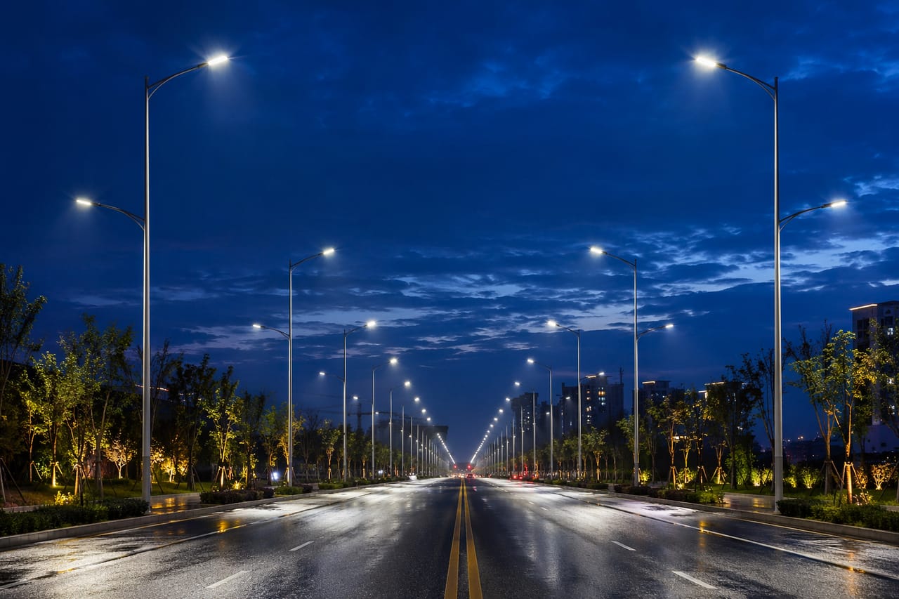
EN 13201 road lighting design follows a fixed sequence: classify the road into an M, C, or P lighting class, read the luminance or illuminance targets that class demands, then iterate pole spacing against the luminaire’s photometric file until every metric passes. This guide walks the full path, with the class tables, typical pole spacings by road type, a worked collector-road example, and the checklist a compliant tender should demand.
Key Takeaways
- EN 13201 defines three class families: M1–M6 for traffic routes (designed in road-surface luminance, cd/m²), C0–C5 for conflict areas, and P1–P6 for pedestrian areas (both in lux).
- Pole spacing typically runs 3.5–4 × mounting height; a 10 m pole with a quality Type III LED optic reaches 35–40 m spacing on an M4 road.
- Four things set achievable spacing: mounting height, the luminaire’s IES/LDT distribution, arm overhang, and the pole arrangement.
- The binding numbers are average luminance, overall uniformity Uo, longitudinal uniformity Ul, and glare (TI) — all verified by calculation, never by rule of thumb.
- LED dimming profiles are explicitly compatible with EN 13201 adaptive-lighting provisions and cut overnight energy on low-traffic routes.
What EN 13201 Is, and Where It Applies
EN 13201 is the European road-lighting standard series, and in practice the global reference: tenders across the Middle East, Africa, Latin America, and Southeast Asia routinely cite it even where it has no legal force. The series splits into five parts:
| Part | Role |
|---|---|
| EN 13201-1 (TR) | Selecting the lighting class from road parameters |
| EN 13201-2 | The performance requirements of each class |
| EN 13201-3 | Calculation methods and grids |
| EN 13201-4 | Field measurement methods |
| EN 13201-5 | Energy performance indicators (PDI, AECI) |
The logic mirrors other application standards like EN 12193 for sports lighting: classify the task first, then read requirements from a table, then prove them by calculation with the real luminaire file. Our glossary entry on EN 13201 gives the two-minute version.
The Three Families of Lighting Classes
M classes: motorised traffic routes
Where drivers are the design user, targets are set in luminance — the light the driver’s eye receives from the road surface, in cd/m². Luminance, not lux, is the correct metric because identical illuminance produces different visibility on light concrete versus dark asphalt.
| Class | Avg luminance | Overall uniformity Uo | Longitudinal Ul | Max TI |
|---|---|---|---|---|
| M1 | 2.0 cd/m² | 0.40 | 0.70 | 10% |
| M2 | 1.5 cd/m² | 0.40 | 0.70 | 10% |
| M3 | 1.0 cd/m² | 0.40 | 0.60 | 15% |
| M4 | 0.75 cd/m² | 0.40 | 0.60 | 15% |
| M5 | 0.50 cd/m² | 0.35 | 0.40 | 15% |
| M6 | 0.30 cd/m² | 0.35 | 0.40 | 20% |
Three metrics beyond the average deserve translation. Uo (overall uniformity) is minimum-to-average across the carriageway: below 0.4, drivers face dark patches where hazards hide. Ul (longitudinal uniformity) controls the bright-dark “zebra” rhythm along each lane that fatigues drivers on long routes. TI (threshold increment) caps disability glare from the luminaires themselves, expressed as the percentage contrast loss they cause.
C classes: conflict areas
Junctions, roundabouts, and shopping streets mix viewing directions, so luminance geometry breaks down. C classes revert to illuminance: C0 = 50 lx down to C5 = 7.5 lx average, with uniformity requirements. A common pattern is a road designed to M3 with its major junctions lifted one step to the comparable C class.
P classes: pedestrian and low-speed areas
Footpaths, residential streets, and parking areas use P1 = 15 lx down to P6 = 2 lx average, each with a minimum-point requirement to prevent dark spots. P classes also introduce semi-cylindrical illuminance options where facial recognition matters for perceived safety.
Selecting the class
EN 13201-1 derives the class from traffic speed, volume, composition, junction density, ambient luminance, and parked-vehicle presence. In practice, municipalities pre-assign classes by road type. Typical mappings:
| Road type | Typical class |
|---|---|
| Motorway / dual carriageway | M1 – M2 |
| Arterial / main road | M3 |
| Collector / distributor | M4 – M5 |
| Residential street | M5 – M6 or P3 – P4 |
| Footpath / cycle path | P4 – P6 |
| Parking areas | P4 – P5 |
| Conflict areas / junctions | C class one step above the adjoining road |
From Class to Pole Layout: The Five Variables
With the class fixed, achievable pole spacing becomes a function of five design variables:
- Mounting height (H). Spacing scales almost linearly with height; the working envelope is 3.5–4 × H between poles. Height itself follows road width: as a rule of thumb, mounting height should be at least equal to the lit carriageway width for single-side arrangements.
- Luminaire photometry. The IES/LDT file decides everything. Roadway optics (IES Type II/III forward-throw) stretch light along the road; a poor distribution can cost 10 m of spacing at identical wattage. This is why serious tenders evaluate photometric files, not wattage lists — the same reason we publish files for the whole SJLD LED street light range — including the municipal-standard 100W LED street light that replaces 250W HPS on 8–10 m poles.
- Overhang and arm length. Positioning the photometric center over the carriageway edge line typically maximizes uniformity; excessive overhang darkens the footpath side.
- Arrangement. Single-side (road width ≤ H), staggered (up to ~1.5 × H), opposite (wide roads), or central twin on dual carriageways with a median.
- Maintenance factor. LED installations design at 0.8–0.9 depending on the cleaning interval and the fixture’s ingress protection; sealed IP65-rated optics justify the higher end.
Typical LED street light starting points
| Road type | Class | Height | LED power | Spacing |
|---|---|---|---|---|
| Residential street | P3–P4 / M5 | 6 – 8 m | 30 – 60 W | 25 – 32 m |
| Collector road | M4–M5 | 8 – 10 m | 60 – 120 W | 30 – 40 m |
| Arterial road | M3 | 10 – 12 m | 120 – 200 W | 35 – 45 m |
| Highway / dual carriageway | M2 | 12 m | 200 – 300 W | 40 – 50 m |
| Interchange / port area | High-mast | 20 – 40 m | Project-specific | Per study |
These scope budgets and bills of quantities. The binding numbers always come from the calculation.
Worked Example: A Collector Road to M4
Consider a 7.5 m two-lane collector road, target class M4 (0.75 cd/m², Uo ≥ 0.40, Ul ≥ 0.60, TI ≤ 15%).
Step 1 — geometry. Road width 7.5 m suggests 8–10 m poles, single-side arrangement (width ≈ height). Choose 9 m with a 1.5 m arm.
Step 2 — fixture pre-selection. A 90 W LED street light at 145 lm/W delivers ~13,000 lm through a Type III medium-throw optic. Wide-input driver, 10 kV surge protection for the exposed feeder, 4000 K with CRI ≥ 70–80 per municipal preference.
Step 3 — first spacing guess. 3.7 × H ≈ 33 m, staggered not required at this width.
Step 4 — calculate. In DIALux with the R3 road-surface reflection table and MF 0.85: iterate spacing 30 → 33 → 36 m. Suppose 33 m passes all four metrics but 36 m fails Ul on the far lane. The design freezes at 33 m, or the optic switches to a longer-throw variant and re-runs.
Step 5 — document. The deliverable is the printed calculation showing class, geometry, luminaire file, MF, and all four passing metrics — the artifact a supervising engineer signs. Archive the IES file itself alongside the report; five years from now, when someone proposes a different luminaire for infill poles, the original file is what makes a like-for-like comparison possible.
This is the exact workflow our engineering team runs when a municipality sends a road cross-section; the DIALux study comes free with quotation.
Road Surfaces, Mesopic Vision, and the Details Behind the Metrics
R-classes: why the asphalt is part of the luminaire
Luminance designs multiply the light arriving at the road by the surface’s reflection table. EN 13201-3 calculations use standardized R-classes — R1 (light, diffuse surfaces such as concrete) through R4 (very dark or polished asphalt) — with R3 the common default for aged asphalt. The consequence is practical: the same pole layout that passes M3 on concrete can fail on fresh dark asphalt, because the surface returns less light to the driver’s eye. When a municipality resurfaces a road, its lighting class compliance changes without a single luminaire being touched. State the assumed R-class in the calculation, and re-check after major resurfacing projects.
Spectrum at low light: the S/P consideration
At the low luminances of residential streets, human vision shifts toward mesopic operation where cooler, higher S/P-ratio light sources yield better perceived visibility per measured unit. This is one argument for 4000 K on traffic routes; it is balanced by the sky-glow and ecological case for 3000 K in sensitive areas. The standard’s metrics are photopic, so treat mesopic benefit as a design consideration rather than a compliance lever.
Energy accounting under Part 5
EN 13201-5 defines two indicators tenders increasingly request: PDI (power density indicator, W per lux per m²), which measures how efficiently the installation converts power into required light, and AECI (annual energy consumption indicator, kWh/m²/year), which captures the operating profile including dimming hours. Two compliant designs can differ by a third in AECI purely through adaptive profiles — which is why the dimming schedule belongs in the tender, not the afterthoughts.
Retrofitting on existing poles
Most real projects inherit pole positions from the HPS era. The design sequence inverts: spacing is fixed, so the free variables become luminaire output, optic selection, arm length, and tilt. Modern optic libraries usually contain a distribution that passes the class at legacy spacing with 40–60% of the legacy wattage; where no optic passes, options escalate from longer arms, to one class step of adaptive dimming at night, to selective pole infill at problem sections only. Demanding the IES files early is what makes this triage possible on paper instead of on the street.
LED-Specific Advantages Worth Designing In
Adaptive dimming. EN 13201 anticipates lowering the class in low-traffic hours. Stepping an M3 road to M4 after midnight via timer or 0–10V/DALI profiles cuts overnight energy roughly in proportion to the dimming depth, with zero civil works. Smart-city nodes extend this to per-pole control and status reporting.
Optics variety on one housing. When existing poles lock the spacing (the retrofit reality), swapping the lens package on the same cobra head housing is often the cheapest path to compliance: the distribution changes, the electrical and mechanical installation does not.
CCT selection. 3000 K reduces sky-glow and ecological impact in sensitive zones; 4000 K remains the visual-performance default for arterials. Specify per road, not per city — the correlated color temperature decision is free at order time and expensive after.
Off-grid sections. Rural connectors and park roads without feeder access can hold the same lighting classes with properly sized solar street lights; the sizing math is its own discipline, covered in our solar street light battery and panel calculation guide.
Verification in the field: EN 13201-4
The calculation proves the design; the commissioning measurement proves the installation. Part 4 defines how: luminance measurements from the driver’s eye position (1.5 m height, 60 m ahead of the measurement field) with a luminance meter or calibrated imaging photometer, or illuminance grids for C and P classes with a lux meter. Measure with the road surface dry and the luminaires aged past their initial hundred hours, record ambient conditions and dimming state, and compare against maintained design values — not initial ones. Municipalities that archive these baseline measurements per road section gain something valuable: every future complaint, accident review, or re-lamping decision can be judged against documented evidence instead of memory.
What a Compliant Tender Should Demand
- Lighting class per road section, stated by the client (not left to bidders)
- Photometric files (IES/LDT) for every offered luminaire, backed by LM-79 test reports
- Point-by-point EN 13201-3 calculation: average, Uo, Ul, TI, and surround ratio, at the declared MF
- Driver specification: input range, surge rating (≥ 10 kV recommended on exposed feeders), power factor ≥ 0.9, dimming interface
- Ingress and impact ratings (IP65+ / IK08+) with test evidence
- Photocell / NEMA / Zhaga socket requirements for future controls
- Warranty terms tied to L70 lumen-maintenance data (LM-80/TM-21)
- Certificate documentation for the destination market (see our CE Declaration of Conformity checklist)
Municipal buyers can cross-check this list against our roadway and municipal lighting solutions page, which maps fixture families to road classes.
Common Roadway Design Mistakes
- Designing in lux on traffic routes. M classes are luminance classes; a lux-only calculation ignores road-surface reflection and viewing geometry.
- Copying spacing from the old HPS layout. LED optics distribute differently; re-calculate rather than assume one-for-one pole reuse is optimal.
- Ignoring TI. A bright, efficient luminaire with poor shielding can pass every illuminance metric and still blind drivers.
- No surround ratio check. Lighting the carriageway while leaving the verge black pushes pedestrians into invisibility at the road edge.
- Uniform CCT and wattage city-wide. Residential streets and arterials have different classes; one SKU everywhere means over-lighting some roads and failing others.
- Forgetting the maintenance factor at handover. Field measurements per EN 13201-4 should be compared against maintained design values, not initial ones.
Frequently Asked Questions
What pole spacing can I expect at 10 m mounting height? With a quality Type III LED optic on an M4 collector road, 35–40 m is realistic for single-side or staggered arrangements. Confirm by calculation; distribution quality moves this figure by ±5 m.
What is the difference between M, C, and P classes in EN 13201? M classes cover traffic routes and are specified in road-surface luminance (cd/m²). C classes cover conflict areas like junctions, specified in illuminance. P classes cover pedestrian and residential areas, also in lux, with minimum-point requirements.
Is EN 13201 mandatory outside Europe? It applies wherever the contract or municipality invokes it, which is common worldwide. Elsewhere it functions as the de facto engineering reference, alongside local codes.
How many watts of LED replace a 250 W HPS street light? Typically 100–120 W of quality LED achieves comparable or better road luminance, thanks to directional optics and stable lumen maintenance. Validate with the IES file at your geometry; wattage-only equivalence claims are unreliable.
Can solar street lights meet EN 13201 classes? Yes, for P and lower M classes, provided the system is sized for the worst-month solar resource and the dimming profile is honest about overnight output. Our solar sizing guide shows the battery and panel math.
Who provides the EN 13201 calculation? Any competent supplier should. We deliver the DIALux study — class, geometry, luminaire files, all four metrics — free from your road cross-section, so the design is verified before any commercial commitment.
The Bottom Line
EN 13201 road lighting design is a disciplined pipeline: class first, targets second, geometry and photometry third, calculation always. The rules of thumb in this guide — 3.5–4 × height spacing, wattage bands by road type — will get a budget and pole count within range, but the luminaire’s IES file and the four class metrics decide the final layout. We publish IES/LDT files for every LED street light we manufacture, so the calculation can start from real photometry rather than brochure claims. Insist on the calculation, specify dimming and surge protection up front, and the installation will pass both the commissioning measurement and the decade of service after it.