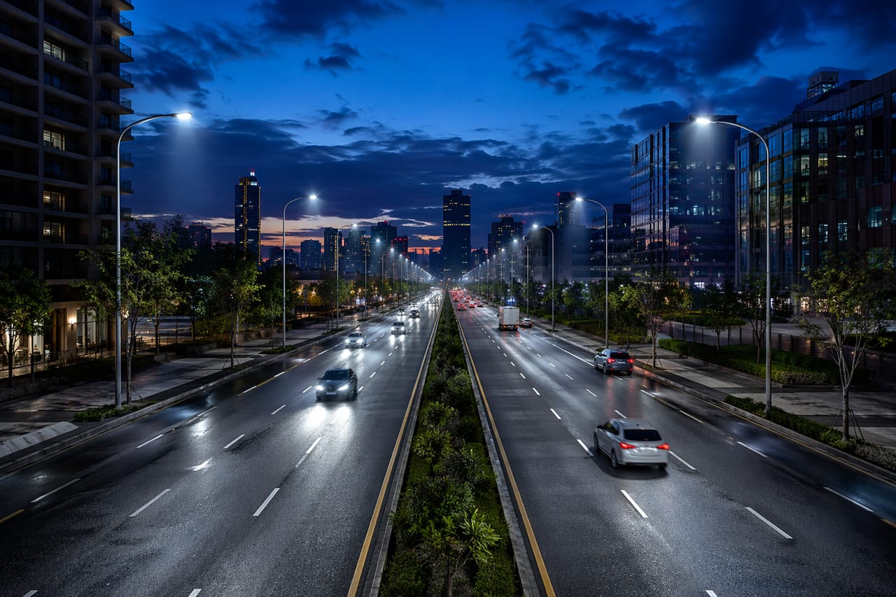
Street light pole spacing runs at roughly 3.5 to 4 times the pole height with a good roadway optic: 18–24 m (59–79 ft) between 4–6 m footpath poles, 30–40 m (98–131 ft) between 8–10 m collector-road poles, and 40–50 m (131–164 ft) between 12 m highway poles. Road width then decides whether those poles stand on one side, staggered, opposite, or in the central reserve.
That is the whole chart in two sentences. The rest of this page lays it out by road type and arrangement, in metres and feet, and shows the arithmetic that checks each row, because a spacing figure without its pole height, road width and lighting class is exactly the kind of number that gets a road built wrong. The rules behind the chart are covered in depth in our EN 13201 roadway lighting design guide; this page is the reference table those rules produce.
Key Takeaways
- Pole spacing is about 3.5–4 × mounting height with a quality Type II/III optic: 24–32 m on 6–8 m residential poles, 30–40 m on 8–10 m collector poles, 35–45 m on 10–12 m arterial poles.
- Road width sets the arrangement: single-side while the lit width is no more than the pole height, staggered up to about 1.5 × height, opposite beyond that, twin-central on dual carriageways.
- The optic caps spacing, not the wattage. Extra watts raise the average; only the distribution fills the dark gaps between poles that fail uniformity.
- A lumen-method check (E = Φ × UF × MF ÷ (S × W)) with UF 0.4, MF 0.8 and 150 lm/W puts a 9 m collector pole at 35 m spacing at roughly 110 W, inside the 60–120 W band.
- Solar heads tighten spacing to about 3–3.5 × height, and junctions, roundabouts, bends and crossings fall outside the chart entirely.
The Street Light Pole Spacing Chart
These are the starting points we use across the site, from the product pages to the design guides. Each row pairs a road type with its typical EN 13201 lighting class, pole height, spacing and LED power.
| Road type | Typical class | Pole height | Pole spacing | LED power |
|---|---|---|---|---|
| Footpaths, cycle paths, car parks, estate access | P-classes | 4–6 m (13–20 ft) | 18–24 m (59–79 ft) | 20–40 W |
| Residential street | P3–P4 / M5–M6 | 6–8 m (20–26 ft) | 24–32 m (79–105 ft) | 30–60 W |
| Collector / distributor road | M4–M5 | 8–10 m (26–33 ft) | 30–40 m (98–131 ft) | 60–120 W |
| Arterial road | M3 | 10–12 m (33–39 ft) | 35–45 m (115–148 ft) | 120–250 W |
| Highway / dual carriageway | M1–M2 | 12 m (39 ft) | 40–50 m (131–164 ft) | 200–400 W |
| Interchange / port | High-mast | 20–40 m (66–131 ft) | Per study | Project-specific |
The chart assumes a sealed IP65 LED street light with a roadway distribution, a maintenance factor of 0.8–0.9, and a straight road section between junctions. Every row is a starting point that the EN 13201 calculation then confirms or corrects.
Arrangement by road width
The second half of the chart is the street light span table by arrangement. Pole height fixes the widest road each arrangement can serve; the spacing band stays with the height.
| Pole height | Single-side: lit width up to | Staggered: lit width up to | Opposite (or twin-central on dual carriageways) | Spacing band |
|---|---|---|---|---|
| 4–6 m (13–20 ft) | 4–6 m (13–20 ft) | 6–9 m (20–30 ft) | Wider than 6–9 m (20–30 ft) | 18–24 m (59–79 ft) |
| 6–8 m (20–26 ft) | 6–8 m (20–26 ft) | 9–12 m (30–39 ft) | Wider than 9–12 m (30–39 ft) | 24–32 m (79–105 ft) |
| 8–10 m (26–33 ft) | 8–10 m (26–33 ft) | 12–15 m (39–49 ft) | Wider than 12–15 m (39–49 ft) | 30–40 m (98–131 ft) |
| 10–12 m (33–39 ft) | 10–12 m (33–39 ft) | 15–18 m (49–59 ft) | Wider than 15–18 m (49–59 ft) | 35–45 m (115–148 ft) |
| 12 m (39 ft) | 12 m (39 ft) | 18 m (59 ft) | Twin-central with a median | 40–50 m (131–164 ft) |
How spacing is measured here. For single-side and staggered layouts, spacing is the distance along the road between one luminaire and the next, whichever side it stands on. For opposite and twin-central layouts, it is the distance between one pair of luminaires and the next pair. Tender documents use both conventions, so state which one a drawing uses before comparing quotes: in a staggered layout the difference is a factor of two in pole count.
The Rules Behind the Chart
Three rules generate every row. The EN 13201 guide derives them and the LED street light selection guide applies them to procurement, so here they are only in summary.
- Spacing ≈ 3.5–4 × mounting height. A 9 m pole lands at about 32–36 m, a 10 m pole at 35–40 m. The footpath row stretches past 4 × at its short end (18 m on a 4 m pole is 4.5 ×), which works only because P-class targets are low and paths are narrow; keep 4 m poles at the 18 m end of the band.
- Height at least equal to lit width for single-side. A pole standing at one kerb has to throw light across the whole carriageway. Once the far kerb is further away than the pole is tall, the far lane goes dim and uniformity fails.
- Arrangement follows width. Staggered layouts serve up to about 1.5 × height, opposite layouts serve wider roads, and twin-central poles in the median light both carriageways of a dual carriageway.
The multiplier holds because a roadway light pool lengthens in proportion to mounting height. Where a road lands inside the 3.5–4 range depends on the optic, the class and the road surface, which is why the chart gives bands.
Why the Optic Moves Spacing More Than Wattage
Average illuminance scales with lumens: double the wattage and the average doubles. Spacing, though, is rarely limited by the average. It is limited by the darkest point between two poles and by the bright-dark rhythm along each lane, the overall uniformity (Uo) and longitudinal uniformity (Ul) that EN 13201 sets per class. Those depend on where the luminaire sends its peak intensity, and that is decided by the lens.
Roadway optics are described by IES lateral distribution types rather than by a single beam angle. Type II is a narrower forward throw that suits narrow roads and paths with poles at the edge. Type III throws further across the road and is the workhorse for collector and distributor roads. Both are asymmetric: they push the peak intensity out along the carriageway at a high angle, so the light pools of neighbouring poles overlap instead of leaving dark bands between them. The classification itself comes from the Illuminating Engineering Society.
A symmetric fixture at the same wattage puts more light at the foot of the pole and less at mid-span. The average can pass while Ul fails, and adding watts only brightens the pools without closing the gap. The roadway hub puts the cost of a poor distribution at up to 10 m of spacing at identical wattage, and closing a 40 m pitch to 30 m means a third more poles.
This is also why a quotation for “100 W street lights” says little. Compare photometric files instead: the IES or LDT file records the actual intensity distribution, and our guide on how to read an IES file shows what to look for. A cobra head street light housing can often take several lens packages, so on a fixed pole layout the fix is usually a different optic, not a bigger fixture.
Checking the Chart: The Lumen Method With Worked Examples
The chart can be sanity-checked by hand with the average-illuminance (lumen) method for roads:
E = Φ × UF × MF ÷ (S × W)
Rearranged to find the luminaire output: Φ = E × S × W ÷ (UF × MF)
- E: target average illuminance on the carriageway (lx)
- Φ: luminaire output (lm)
- UF: utilisation factor, the share of luminaire lumens that land on the lit width. We use 0.4 for a roadway optic on a single-side layout.
- MF: maintenance factor, 0.8 here (the low end of the 0.8–0.9 range for sealed IP65 LED)
- S: spacing between luminaires (m)
- W: lit width served by each luminaire (m)
Wattage follows as Φ ÷ efficacy, and we use 150 lm/W.
A caveat on lux targets for M-class roads
EN 13201 M classes are specified in road-surface luminance (cd/m²), not illuminance, because the same lux looks brighter on pale concrete than on dark asphalt. The lumen method works in lux, so it needs a planning equivalent. On a dark R3-type asphalt, with an average luminance coefficient of about 0.07, average luminance is roughly 0.07 × illuminance, which puts 1 cd/m² at about 14 lx. The planning targets below round those figures up to the upper class in each band:
| Road type | Class band | Luminance (upper class) | ≈ Illuminance on R3 asphalt | Planning target used |
|---|---|---|---|---|
| Residential street | M5–M6 / P3–P4 | 0.50 cd/m² (M5) | ≈ 7 lx | ~10 lx |
| Collector road | M4–M5 | 0.75 cd/m² (M4) | ≈ 11 lx | ~15 lx |
| Arterial road | M3 | 1.0 cd/m² | ≈ 14 lx | ~20 lx |
| Highway / dual carriageway | M1–M2 | 1.5–2.0 cd/m² | ≈ 21–29 lx | ~30 lx |
These equivalents are for scoping only. Luminance depends on observer position, surface and luminaire geometry, and the lumen method ignores uniformity and glare entirely. The final check is always the EN 13201-3 luminance calculation with the real photometric file.
Example 1: residential street, 6 m pole
Inputs: 6 m (20 ft) pole, 7 m (23 ft) lit width, 24 m (79 ft) spacing, ~10 lx target, UF 0.4, MF 0.8, 150 lm/W.
Φ = 10 × 24 × 7 ÷ (0.4 × 0.8) = 1,680 ÷ 0.32 = 5,250 lm
Wattage = 5,250 ÷ 150 ≈ 35 W, so a 30 W or 40 W tier.
The result sits inside the residential band of 30–60 W, at its lean end because 6 m is the lowest residential height. The geometry needs attention, though: a 7 m lit width is 1 m past the single-side rule for a 6 m pole. Either an arm that brings the luminaire out over the kerb or a staggered layout is needed, and the calculation decides which one passes the far-lane uniformity.
Example 2: collector road, 9 m pole
Inputs: 9 m (30 ft) pole, 10 m (33 ft) lit width, 35 m (115 ft) spacing, ~15 lx target, UF 0.4, MF 0.8, 150 lm/W.
Φ = 15 × 35 × 10 ÷ 0.32 = 5,250 ÷ 0.32 ≈ 16,400 lm
Wattage = 16,400 ÷ 150 ≈ 109 W, so a 100 W or 120 W tier.
That lands in the collector band of 60–120 W and matches the envelope on our 100W LED street light page: 8–10 m poles at 30–40 m for M4–M5 collector roads. At 10 m width on a 9 m pole the road is again just past single-side, so a staggered layout (good up to 13.5 m) is the safer first model.
Example 3: dual carriageway, 12 m twin-central poles
Inputs: 12 m (39 ft) poles in the central reserve with twin arms, each luminaire lighting one 8 m (26 ft) carriageway, 45 m (148 ft) between pole pairs, ~30 lx target, MF 0.8, 150 lm/W.
The utilisation factor needs a judgement here. With a narrow median, the arm puts the luminaire over the inner edge of the carriageway, much like a kerbside pole, so UF 0.4 holds. A wide planted median wastes part of the throw on the verge, so we take UF 0.3.
- UF 0.4: Φ = 30 × 45 × 8 ÷ (0.4 × 0.8) = 10,800 ÷ 0.32 = 33,750 lm → about 225 W
- UF 0.3: Φ = 10,800 ÷ (0.3 × 0.8) = 10,800 ÷ 0.24 = 45,000 lm → 300 W
Per luminaire, that is roughly 230–300 W, inside the highway band of 200–400 W. The median width moves the answer by a full wattage tier, and that is the kind of detail a pole spacing chart cannot see.
Summary of the checks
| Case | Height | Width per luminaire | Spacing | Target | UF | Result | Chart band |
|---|---|---|---|---|---|---|---|
| Residential | 6 m | 7 m | 24 m | ~10 lx | 0.4 | ≈ 35 W | 30–60 W |
| Collector | 9 m | 10 m | 35 m | ~15 lx | 0.4 | ≈ 110 W | 60–120 W |
| Arterial (quick check) | 11 m | 11 m | 40 m | ~20 lx | 0.4 | ≈ 185 W | 120–250 W |
| Dual carriageway | 12 m | 8 m | 45 m | ~30 lx | 0.3–0.4 | ≈ 230–300 W | 200–400 W |
All four land inside their bands. That shows the chart is consistent at 150 lm/W, not that any specific road passes its class.
Solar Street Light Poles: Why Spacing Tightens
Solar street lights follow the same photometry as mains fixtures, but they are normally spaced at about 3–3.5 × mounting height rather than 3.5–4 ×. On a 6 m pole that is 18–21 m (59–69 ft); on 8 m, 24–28 m (79–92 ft).
Two things drive the tighter pitch. Solar heads run lower peak lumens than mains fixtures of the same class, because every lumen has to be paid for in panel and battery. And most solar systems run a dimming profile that steps output down after the evening peak, so the layout needs enough overlap to hold uniformity at the dimmed level, not only at full output.
So a solar scheme often needs more poles than the mains layout on the same road. Size the energy system against the worst-month sun first, then set spacing from what the head delivers. Our solar street lights guide covers the sizing arithmetic and the solar-specific installation rules (shading, panel orientation, battery placement).
Where the Chart Does Not Apply
The chart describes straight, continuous road between junctions. Four situations break its assumptions, and each needs its own layout.
| Location | Why the chart fails | What changes |
|---|---|---|
| Junctions | Traffic arrives from several directions, so luminance geometry no longer describes what drivers see | Designed as a C-class conflict area, usually one step above the adjoining road, in illuminance |
| Roundabouts | Circular travel path and entry conflicts | Poles on the outer perimeter, lighting extended along each approach so drivers adapt before entry |
| Bends | Light from inside-bend poles falls behind the driver’s line of sight; visual guidance breaks | Poles on the outside of the curve, spacing reduced as the radius tightens |
| Pedestrian crossings | The pedestrian must be lit against the road, including vertical faces | Dedicated luminaires positioned on the approach side so the pedestrian is lit from the driver’s direction |
Where a junction interrupts a run, reset the pitch so a pole lands at the conflict point, usually by shortening one or two spans on each approach.
From Chart to Verification
The chart gets a project to a budget, a pole count and a first layout. It does not get it to compliance. For that, EN 13201-3 defines the calculation: a point grid over each lane, the luminaire’s photometric file, the declared maintenance factor and road-surface class, and results for average luminance, Uo, Ul and threshold increment (TI) against the class. The standard itself is published through CEN and national standards bodies.
What to prepare before the calculation:
- Cross-section: carriageway widths, lanes, footpaths, median and verge.
- Lighting class per road section, set by the client or authority rather than by bidders.
- Pole constraints: fixed positions on a retrofit, setback from the kerb, arm lengths available.
- Road surface (assumed R-class) and the maintenance factor to be declared.
- Colour temperature per road, since residential streets and arterials rarely share one (3000K for residential and sensitive areas, 4000K for arterials and industrial roads). Municipal and EPC buyers can see how these road classes map to fixture families on our roadway and municipal lighting page, and the full SJLD LED street light range runs from 20 W to 480 W across eight series, with IES/LDT files for DIALux, Relux and AGi32.
The Bottom Line
Use the chart to scope: pick the row for your road type, check the arrangement against road width, and run the lumen method to confirm the wattage band. Then stop trusting rules of thumb, because the class is decided by uniformity and glare, which only the photometric calculation shows. Send us your road cross-section and target class and our engineers return the EN 13201 roadway study free with the quotation, with the spacing, fixture schedule and IES files it was built on.
FAQ
How far apart should street light poles be? About 3.5 to 4 times the mounting height with a quality roadway optic. That gives 24–32 m (79–105 ft) for 6–8 m residential poles, 30–40 m (98–131 ft) for 8–10 m collector-road poles, 35–45 m (115–148 ft) for 10–12 m arterial poles and 40–50 m (131–164 ft) for 12 m highway poles. The EN 13201 calculation with the actual photometric file sets the final figure.
What is the distance between street light poles in feet? Typical ranges are 59–79 ft on 13–20 ft footpath and car park poles, 79–105 ft on 20–26 ft residential poles, 98–131 ft on 26–33 ft collector-road poles, 115–148 ft on 33–39 ft arterial poles, and 131–164 ft on 39 ft highway poles. These are the metric bands converted and rounded, so design in one unit system and convert only at the end.
What pole height do I need for my road width? For poles on one side only, the pole should be at least as tall as the lit carriageway width: a 7 m road wants a pole of 7 m or more. A staggered layout stretches that to about 1.5 times the height, so 8 m poles can serve roads up to about 12 m wide. Wider roads need poles on both sides, and dual carriageways usually take twin-arm poles in the median.
What wattage goes on a 9 m street light pole? On a collector road at 30–40 m spacing, typically 60–120 W. The lumen check for a 10 m lit width at 35 m spacing and about 15 lx gives roughly 110 W at 150 lm/W with a utilisation factor of 0.4 and a maintenance factor of 0.8. The optic can move that answer a full tier either way, which is why the photometric file matters more than the wattage.
Why are solar street lights spaced closer together? Solar heads typically run lower peak lumens than mains fixtures and usually dim after the evening peak to protect the battery. To hold uniformity at the dimmed level, spacing drops to about 3–3.5 times the mounting height, around 18–21 m on a 6 m pole. A solar scheme often needs more poles than the mains layout it replaces.
Does staggered spacing mean the distance between poles on the same side? Not in this chart. Here staggered spacing is measured between consecutive luminaires along the road, whichever side they stand on, so poles on the same side sit at twice that distance. Some specifications measure along one side only, which doubles the pole count at the same quoted figure, so confirm the convention before comparing quotes.